Table of Contents
- Rotor Structural Integrity and Fatigue Damage Mechanisms at High Environmental Speeds
- Condensation-Induced Liquid Droplet Erosion in Mechanical Vapor Recompression (MVR) Rotors
- Thermal and Mechanical Fatigue Effects in Frequent Stop-Go Working Conditions
- Fouling / Deposit Formation
- Casing Area Contamination Due to Seal Leakage
During our Mechanical Vapor Recompression (MVR) field visits, we encounter similar mechanical and operational situations in different sectors. We consider it important to share these observations with you, valued users who operate MVR systems. Our aim is not to provide a malfunction report; to draw attention to early symptoms that may affect system health and to strengthen the preventive approach.
Rotor Structural Integrity and Fatigue Damage Mechanisms at High Environmental Speeds
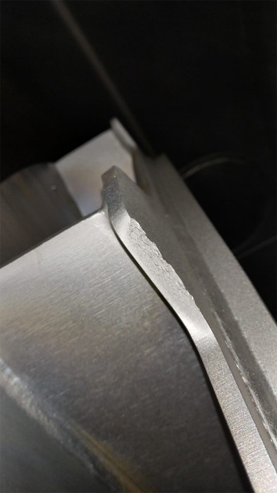
Material fatigue is an inevitable process in all fan systems that operate for a long time. For this reason, wear, local thinning or small material breaks on the rotor over time are considered normal in general fan applications. In our examination in the field, it was clearly seen that the rotor in question was a piece of equipment that had fulfilled its duty for many years. This situation is in the literature; The phenomenon of rotor fatigue and local breakage is commonly associated with the high-cycle fatigue (HCF) mechanism in high-speed rotating impellers and has been reported extensively (e.g. Fatigue failure of centrifugal compressor impellers).
https://www.sciencedirect.com/science/article/abs/pii/S1350630723005460. However, considering this situation as “normal” does not mean that the system is working properly. On the contrary, such findings indicate that the rotor has largely completed its structural life and can no longer continue its duty with sufficient safety and efficiency. In summary, the cause may be natural; but the result is negative in terms of system performance and operational safety.
This article may interest you. What is a MVR Blower? Working Principle, Application Areas
Mechanical Vapor Recompression (MVR) and turboblower systems are machines operating at high environmental speeds, and the rotor, blade and fasteners are all the result of serious engineering calculations.
For example, considering a rotor with a diameter of 1,500 mm, the radius is 0.75 m. Assuming that the rotor rotates at 3,500 rpm, the angular velocity
ω = 2π·n / 60 = 2π·3500 / 60 ≈ 366 rad/s.
In this case, the peripheral speed at the rotor tip
It reaches v = ω·r = 366 · 0.75 ≈ 275 m/s.
The centrifugal acceleration occurring at the same point is
a = ω²·r = (366)² · 0.75 ≈ 100,000 m/s².
The approximate circumferential stress created by this load in the rotor material is expressed as follows:
σ ≈ ρ · ω² · r²
Assuming ρ ≈ 8,000 kg/m³:
σ ≈ 8,000 · (366)² · (0.75)² ≈ 590 MPa
These values clearly show why material selection is critical:
| Material Type | Yield Strength (MPa) | Performance Assessment |
| Carbon Steel (S235–S355) | 235 – 355 | Within yield zone (High Risk) |
| AISI 304 | ~215 | Not Suitable |
| AISI 316 | ~290 | High yield & deformation risk |
| Super Duplex | 550 – 650 | Safe / Suitable |
At this point, the problem is not just speed. When designing and operating such systems, it becomes critical how long the rotor can withstand these speeds and whether the material selection is made accordingly. The following typical material values clearly show this difference:
As can be seen from this comparison, carbon steels and standard stainless steels tend to yield and fatigue earlier at this level of environmental speeds, while materials with high yield and fatigue strength, such as super duplex, can withstand these loads more safely. Therefore, one of the factors that determine MVR system health is not only operating conditions; It is the correct integration of the correct material information suitable for these conditions into the system from the beginning.
Condensation-Induced Liquid Droplet Erosion in Mechanical Vapor Recompression (MVR) Rotors
In MVR systems, a significant portion of the damage on the rotor occurs due to the effect of liquid droplets carried as a result of condensation at high environmental speeds. If the condensation formed at the evaporator outlet or within the system cannot be adequately separated or if drainage is not fully ensured, the liquid accumulated in the volute may soon hit the rotor blades. Such impact events lead to severe erosion, local ruptures and instabilities, as observed in many cases in the field; this mechanism affects the performance and safety margin of not only the rotor but the entire MVR system.
You can also review a study on this subject, where the effects of water droplet impact on high-speed impeller surfaces are well explained with beautiful experiments and clear visuals. (e.g. Experimental Investigation on the Erosion Resistance Characteristics of Compressor Impeller Coatings to Water Droplet Impact – https://www.mdpi.com/2079-6412/15/7/767).
Thermal and Mechanical Fatigue Effects in Frequent Stop-Go Working Conditions
Frequent start-stop operating conditions in MECHANICAL VAPOR RECOMPRESSION (MVR) systems create a continuous heat input and heat output on the rotor. These repeated thermal cycles cause different expansions in different regions of the rotor. This thermal fatigue, which accumulates over time, especially in the wing-hub and weld areas, paves the way for structural weakening. Combined with flow and centrifugal loads, this increases the risk of progressive damage.
Fouling / Deposit Formation
Fouling (Deposit Formation) on the Rotor Inner Surface
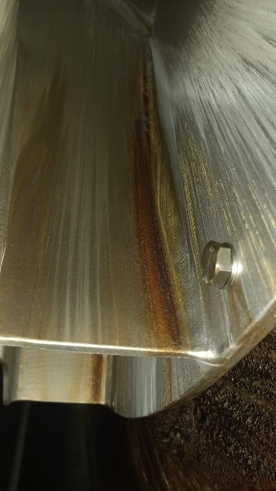
During the field inspection, significant deposits and fouling were detected on the rotor inner surfaces. Currently, no vibration problems have been reported by the business. It is considered that this is due to the fact that the debris is rigidly attached to the rotor surface due to the system operating at high peripheral speeds and does not yet cause a significant imbalance. In this respect, it can be said that the system is lucky in the short term under current conditions.
However, leaving such deposits on the rotor for a long time poses serious risks. The rupture or displacement of deposits over time may cause sudden and unpredictable imbalances. In addition, the chemical components contained in the debris have the potential to cause local wear, corrosion or surface damage on the rotor material. For these reasons, it is recommended that these deposits be cleaned without delay.
When possible sources are evaluated, the content and filtration status of the fluid feeding the spray nozzle positioned in front of the rotor should be specifically checked. If this fluid is not clean enough, it is possible for the transported contaminants to form deposits directly on the rotor surface. Otherwise, it has been evaluated that the pollution may have been dragged from the evaporator or process line and carried to the fan system. For this reason, it is recommended to make an evaluation from the perspective of the entire system, not just the fan equipment, and to clarify the source of the debris together with the process manager or system supplier.
Casing Area Contamination Due to Seal Leakage
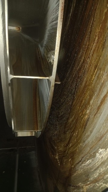
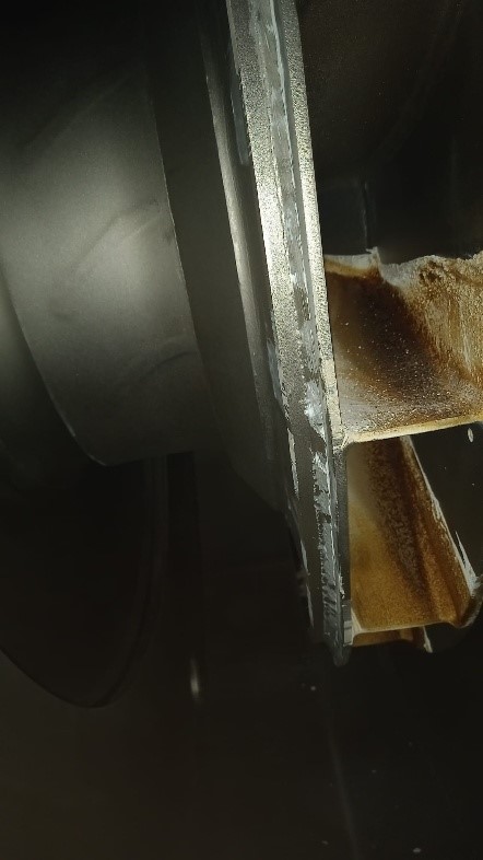
In this case, it was evaluated that the pollution observed in the volute area behind the rotor was caused by seal leakage. The system examined is an MVR application operating under vacuum, and when the system was put into operation, leakage in the seal and above normal temperature in the drainage line were observed. It was thought that this situation caused the escaping fluid to accumulate in the casing area over time.
In line with current observations, it is first recommended to add a suitable filtration element to the sealing line. In addition, it was recommended to check and replace carbon rings that were considered to have lost their sealing performance. Monitoring the system after filtration and carbon ring replacement; If pollution continues, it is recommended that the fan and process sides be re-evaluated together.
In this study, we tried to briefly and concisely share with you some of the technical situations we observed during our field visits. Our aim is to strengthen early awareness and preventive approach rather than post-failure intervention.
It should not be forgotten that Mechanical Vapor Recompression (MVR) systems operate at high speeds and tight tolerances. For this reason, regular inspection of the rotor, sealing areas and internal surfaces, especially during planned shutdowns or in periods of 3-4 months, is critical for system health. A seemingly minor symptom may herald serious performance losses in the future.
If you have different opinions, similar or different situations you have encountered in the field, or special issues you would like to be addressed technically, do not hesitate to share them with us. If you wish, you can also submit your existing rotor images or field findings. We will be happy to support you in cases that require technical evaluation.
We are always ready to evaluate together to ensure the safe, efficient and sustainable operation of your systems. You can contact our Efsan Makina team immediately.
tags :
More about the sector and our business